First Pictures |
 |
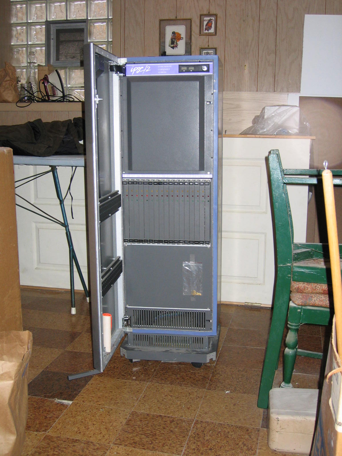
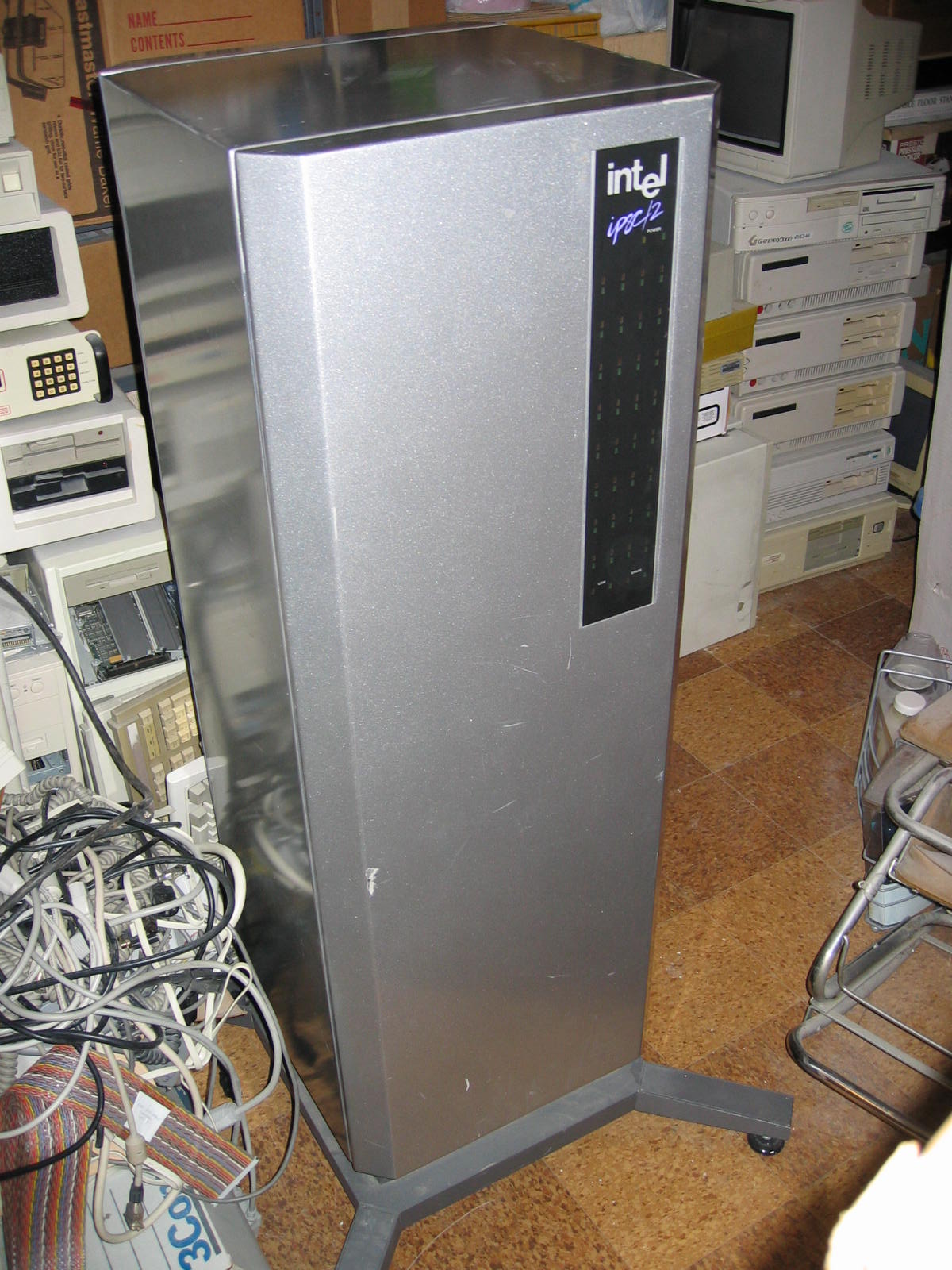
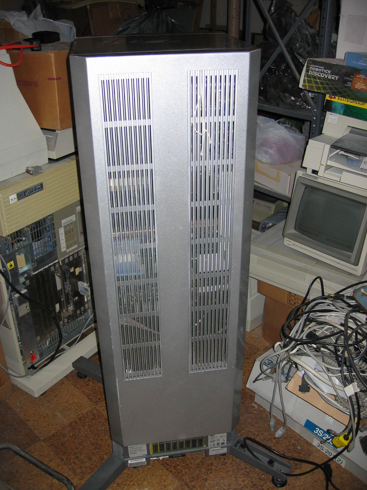
These two were the first pictures taken, fresh after the capture of the machine from deep in Missouri. |
 |
They were trophy shots for my father to show off at work, and before the machine had been cleaned or the legs put on. Also gives reference to the height of the thing. |
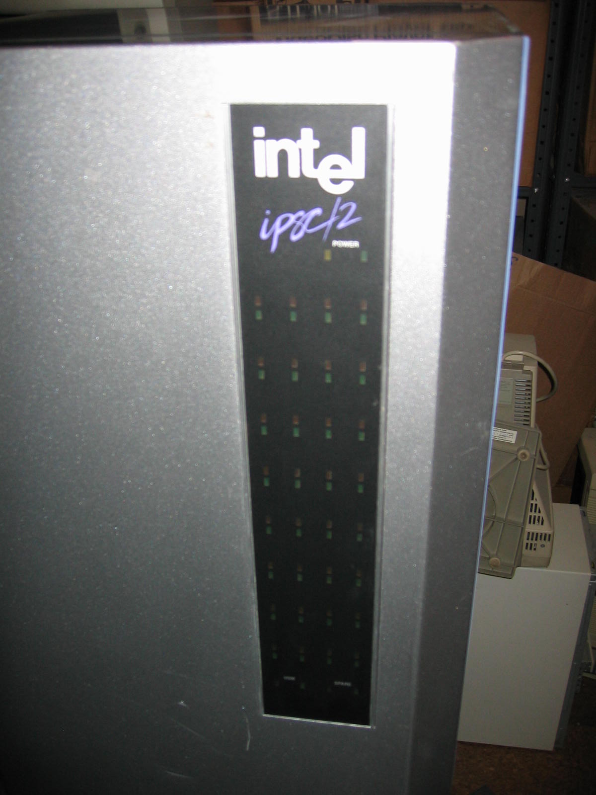
Front panel |
 |
The unit has status lights on the outside of the front cover, which are opticoupled to the lights on the front panel inside. |
 |
|
 |
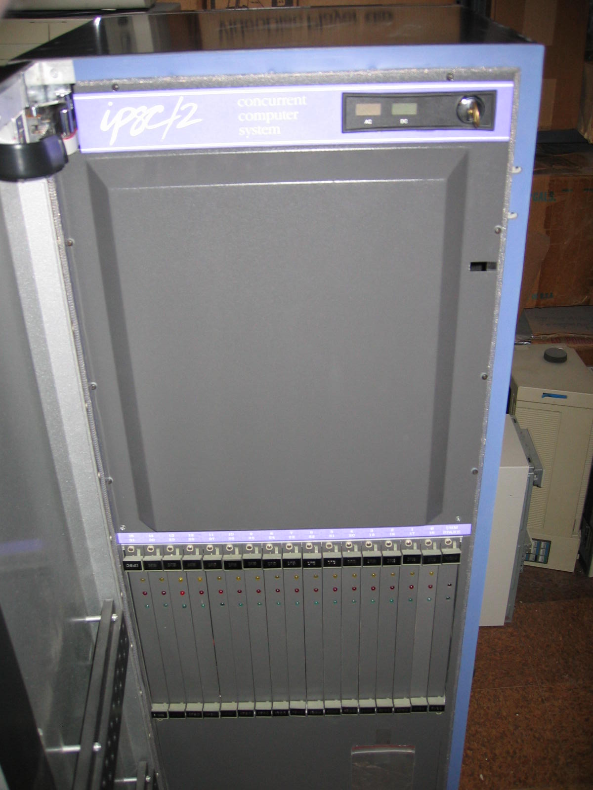
This machine has sixteen 386 processors, each with 387 coprocessor, and it appears the cabinet was designed to expand to 32. |
 |
|
Rear panel and workings |
 |
At first I had to remove a panel in the front to access the rear cover latch, but now it can be opened by a string. |
 |
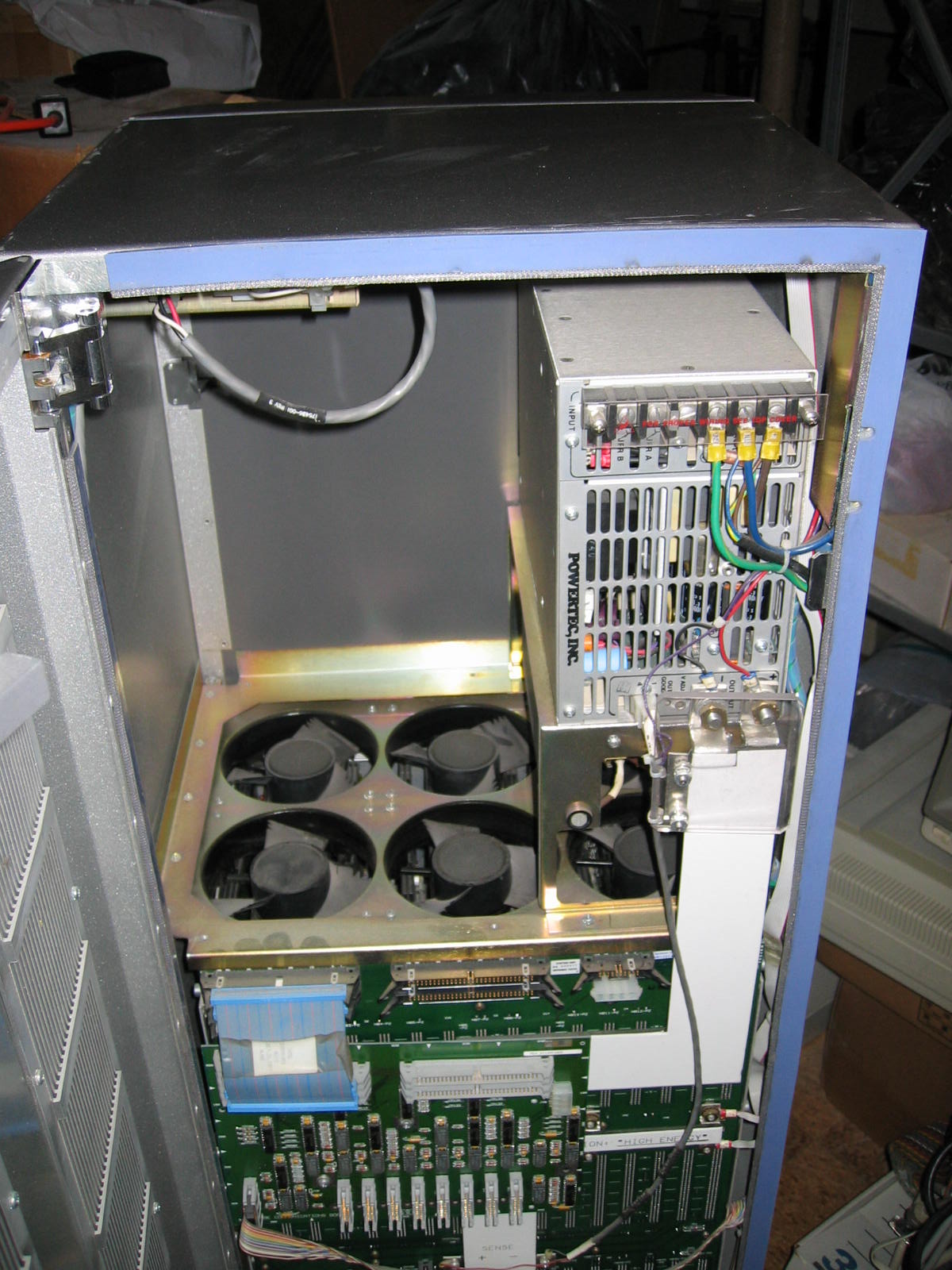
Here is the area for external connections. It does run on 240 V power, which was not difficult to wire up, and the correct plug was obtained by my father at work. There is a DB 25 connector which is connected to a 20 strand braided ribbon cable inside, and eight plastic knockouts which have nothing behind them. |
 |
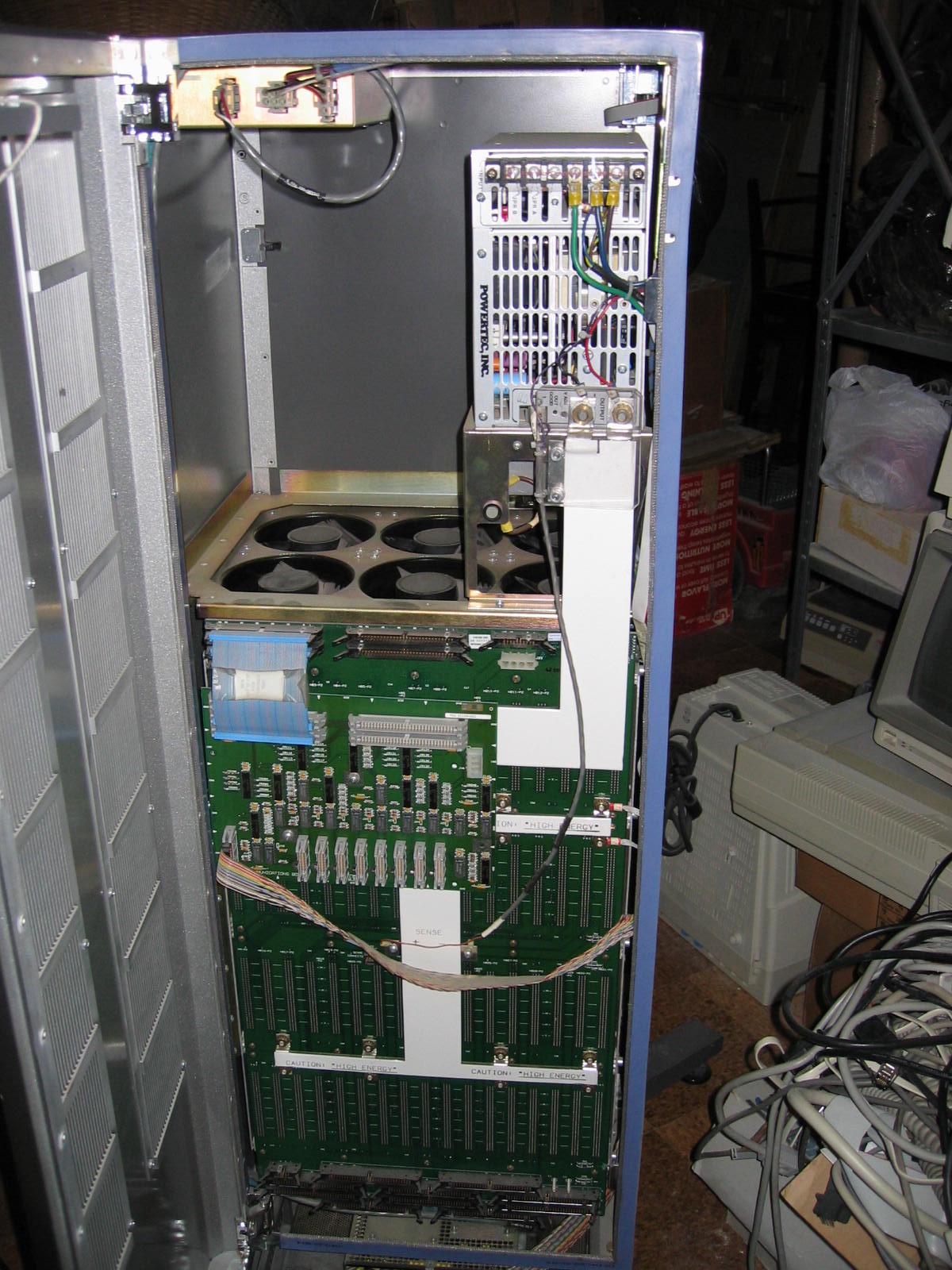
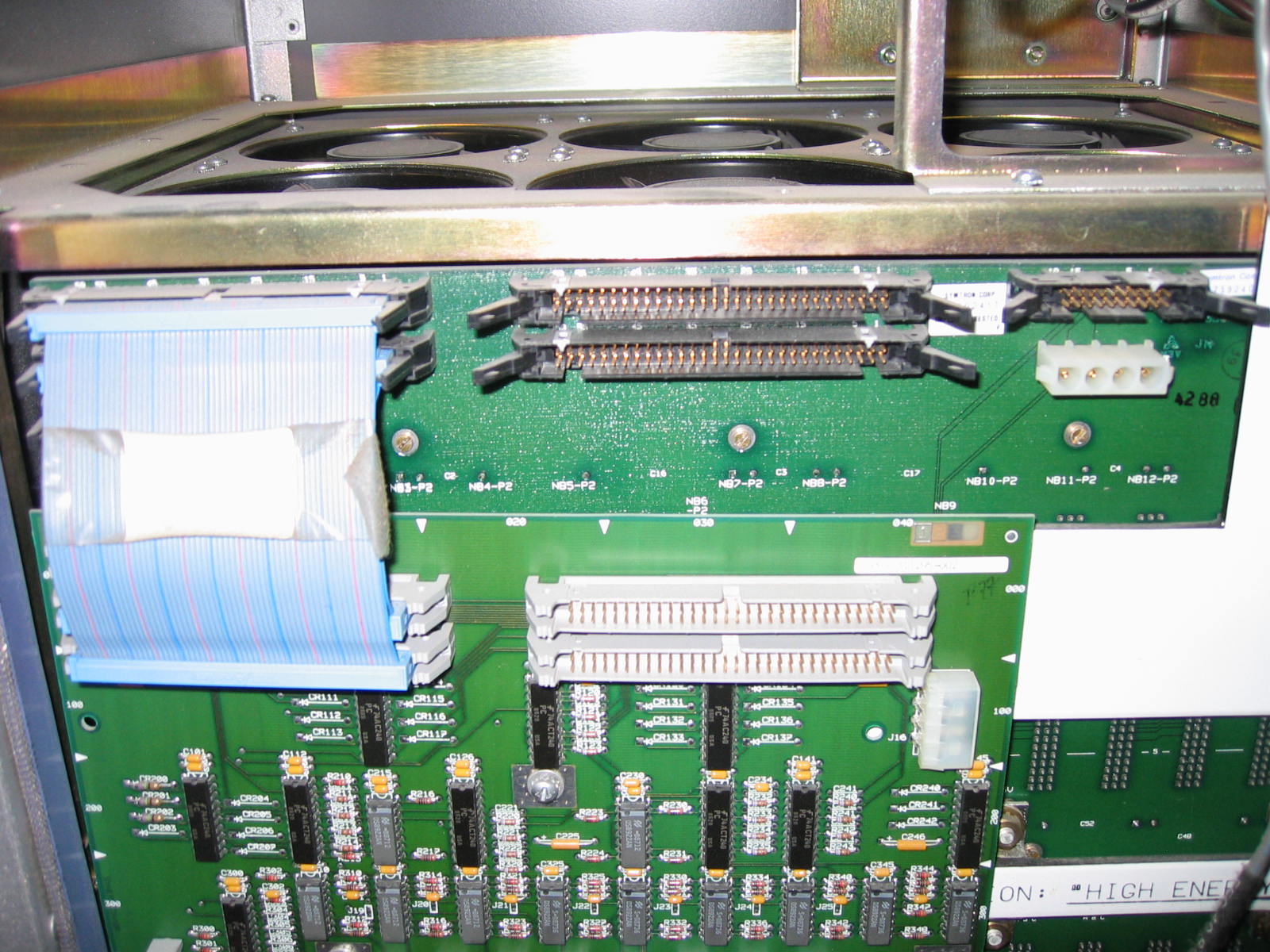
Looking inside the rear, the upper area houses the power supplies and airspace for cooling, and there are two electronics boards, the main connecting plannar and a smaller board labeled "cube communications board."
It has been noted in other online sources that the nodes in this unit are internally networked into a hypercube, but this is built into the hardware and hidden from a programming perspective. |
 |
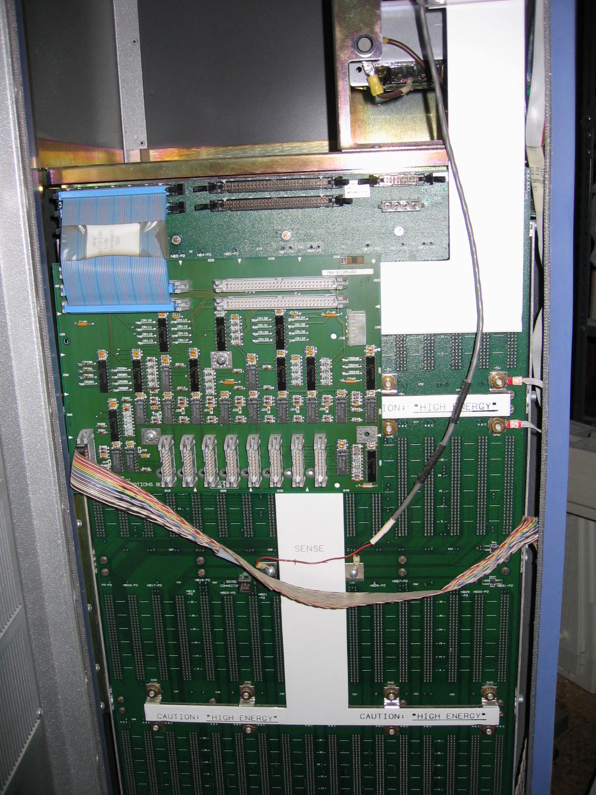
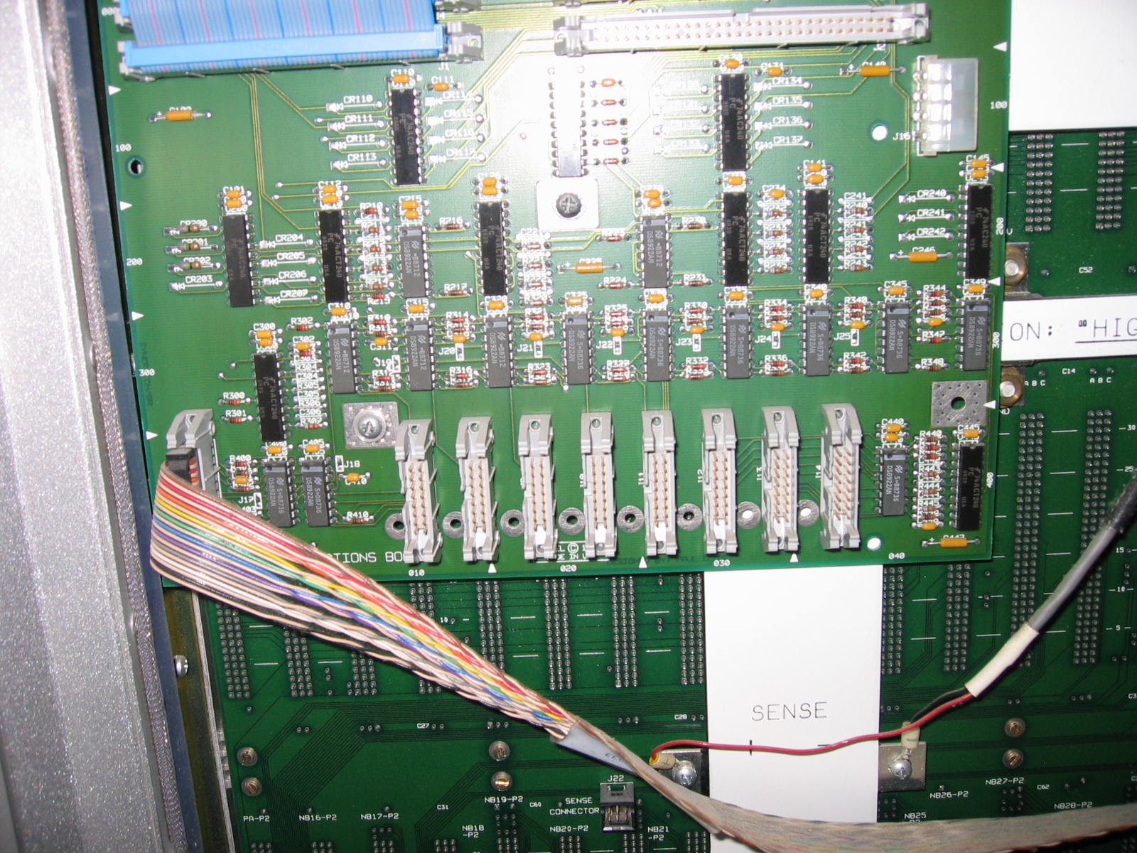
The cube com board is only connected to the main plannar by two overlapping, and very wide ribbon cables (blue). |
 |
The braided ribbon cable connects to a 20 pin connector on the cube com board, which is next to eight 16 pin connectors, unused. Possible correlation to the knockouts near the foot of the machine. |
 |
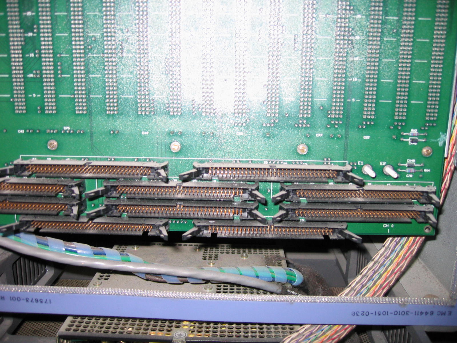
Near the bottom of the plannar is a selection of unused wide connectors. |
 |
The following are more closeups of interesting parts of the electronics.
Other things to note: The machine powers on smoothly. There is no onboard storage, which implies that all programming and data must be loaded after each power on. The ribbon cable that connects to the exterior port is comprised of ten twisted pair, and appears to be crimped into the port right-justified, leaving the leftmost pins unconnected. |
 |
|
 |
|